-
Space oriented filters. Description
Until now, only the amplitude of the results was treated. The phase
(or space direction) of the signals can also have a significant role.
General description:
The transformations of Sobel and Prewitt are very effective tools to privilege
a particular direction during the analysis: They make it possible to be
focused on the variations of the image like on their space directions.
Moreover, they are carried out very simply, by convolution with the
corresponding matrices:
Sobel:
[ - 1 0 1 ]
[ - 2 0 2 ]
[ - 1 0 1 ] |
Prewitt:
[ 1 1 1 ]
[ 1 -2 1 ]
[ - 1 -1 -1 ] |
The problem is that these transformations make disappear almost all
information on the amplitude (which can however be found by thresholding).
But the wavelets also make it possible to privilege a particular direction
during the analysis. Thus, the wavelet known as of Gabor (similar to a
Gaussian signal) is usable to this end.
Directional decompositions:
-
What is a directional decomposition?
A directional decomposition is a decomposition multi-oriented, multi-scale
which can be useful for many systems of image processing.
The transformation is that of a typical decomposition by wavelets.
The diagram below shows synoptic decomposition:
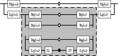 |
The initial image is first of all filtered by H0 and L0.
The result after H0 corresponds to the coefficients on scale 1 and
the result after L0 is the " residue " on scale 1.
The next results are obtained in the same way, with K+1 oriented filters
(B0 with BK) and L1 for the residue. The coefficients obtained (Bi) are
the oriented decomposition, on scale N, of the source image. |
EXAMPLE:

|
The image is a white disc on a black background.
Here, 4 orientations and 2 scales of decomposition are used.
The position of each image is similar to those used in wavelet decomposition.
The remaining image, at the top, on the left is the residue, after
the low-pass filter. |
 |
EXAMPLE:

|
Here, 2 orientations and 2 scales of decomposition are used.
The high-pass coefficients of the initial decomposition (H0)
are visible down, on the right.
The remaining image, at the top, on the left is the residue, after the
low-pass filter. |
 |
The example above is done with the filters drawn below:

L1 is a not oriented low-pass filter, to extract the residues which
will be analyzed within the next iterations. H0 and L0 are not oriented,
high-pass filters (coefficients) and low-pass (to produce residues, before
the analysis of the orientation).
-
What are the advantages and disadvantages of an oriented decomposition?
This kind of angular decomposition allows a representation independent
of the scale and the orientation. We can also notice the absence " of frequential
images " (alias) on significant scales (contrary to the wavelets), which
makes the further operations simpler.
This decomposition produces redundant information, which leads to a
lack of time.
In comparison with other transformations, close to the wavelets:
| . |
Oriented Decomposition |
Gabor Transform 2D |
Discrete Cos Transform |
time/
frequency |
yes |
yes |
|
invariant by translation
(no alias) |
yes
(approx) |
not |
not |
with oriented
filters |
yes |
yes |
not |
invariant by
rotation |
yes
(approx) |
not |
not |
| complete |
4k/3 > 1
= > redundant |
1 |
1 |